
This is UltimateRPA Documentation
UltimateRPA Inspector is a tool designed to analyze the graphical interface of a robotic application. It is the primary tool in the creation and debugging of a robotic script for UltimateRPA Robot. With UltimateRPA Inspector, a Python expression can be created that uses the urpa.py interface to identify a GUI element in the graphical interface of a robotic application.
UltimateRPA Inspector is designed for operating systems Microsoft Windows 7 (NT 6.1) through to Microsoft Windows 10 (NT 10.0). You can launch the Inspector by launching the Inspector.exe application.
You may obtain the UltimateRPA license free of charge for non-commercial use, or test whether the tools meet your expectations and then switch to a license for commercial use.
Both the commercial and non-commercial licenses are issued for one year and offer the same tools, features and documentation. If you opt for a non-commercial license, whenever you start up tools the license will be validated against our license server. This is not the case with a commercial license.
A commercial license is limited to one device on which it is run, regardless of the number of robotic automation executed. Put simply, you can run dozens of robotic processes on one computer with a single license.
There is no limit to the number of devices covered by a non-commercial license.
The full text of the General Terms and Conditions can be found in General_terms_and_conditions.rtf, in the directory where Inspector.exe is located.
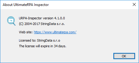
To view the details of license.lic (the license file), you need to go to the UltimateRPA Inspector Help Menu.
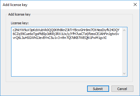
If license.lic is not located in the directory with Inspector.exe, after running the application you must enter a valid license key, or the content of a valid license.lic file, into the "License Key" edit box in the "Add License Key" dialog, and then click Submit. If the license key is valid, clicking the Submit button will create a license.lic file in the directory of Inspector.exe and UltimateRPA Inspector will run in licensed mode.
UltimateRPA Inspector's basic function is to detect the current properties of the individual elements of the graphical user interface (GUI) in the application to be operated by the Robot. While creating and debugging a robotic script, the user must specify the GUI elements and their properties as identified in a robotic application's GUI window and use those identified GUI elements to refer in the scripts for performing actions. If a GUI element property is modified in the course of robotic script preparation then to successfully identify a GUI element its identifiers are to modified as used in the scripts.
After identifying a GUI element of a robotic application you can create a Python expression for that GUI element using the controls on the right side of the UltimateRPA Inspector dialog box. This Python expression should be used to identify a GUI element in the robotic script. When the robotic script is run, this expression represents the GUI element in the robotic application.
The robotic application's graphical interface is analyzed, or the robotic application's GUI element is selected, using crosshair in the top left of the UltimateRPA Inspector dialog box. By grabbing (pressing and holding down the left mouse button) the crosshair icon and dragging the mouse over an area in the robotic application, the GUI elements of its graphical interface are highlighted according to the current crosshair position. At the point where the crosshair (the mouse) is positioned, the values on the right side of the UltimateRPA Inspector dialog box (or the values in the Value column) are updated. The values in the Value column are the attribute values of the currently selected GUI element of the robotic application. Releasing the left mouse button ends the analysis of the robotic application's graphical interface and updates the tree on the left side of the UltimateRPA Inspector dialog box according to the last crosshair position (according to the last GUI element selected). In the GUI element tree, the GUI element last marked in the robotic application then remains highlighted.
If you press the Ctrl key before grabbing the crosshair icon and release the Ctrl key after grabbing the crosshair icon, you can use the mouse buttons to control the robotic application (the mouse buttons can be used during an analysis of the robotic application's graphical interface). This feature can be used to analyze the elements of a robotic application's graphical interface that are accessible only by clicking on another element or by keeping the focus on another element (e.g. a website pop-up menu). In this case, the Ctrl key needs to be pressed to end the analysis of the robotic application's graphical interface.
If a tree of the robotic application's GUI elements is created on the left side of the UltimateRPA Inspector dialog box, crosshair movement can be replaced by manually selecting individual tree elements. When individual nodes of the GUI element tree are selected, values in the Value column will be updated and the corresponding GUI element will be highlighted in the robotic application's graphical interface.
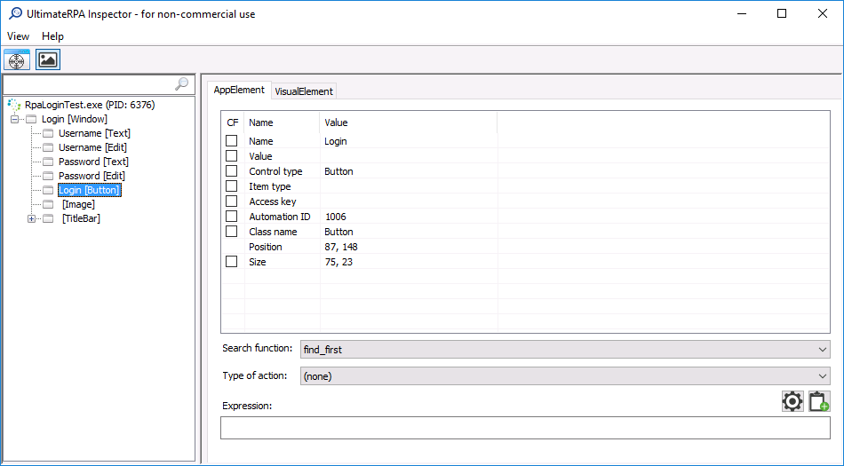
On the left side of the UltimateRPA Inspector dialog box, a GUI element tree is displayed, in which the root represents a process tied to the robotic application. The tree root description comprises the name of the robotic application process and its current PID. The inner nodes of the tree on the first layer are always GUI elements representing a robotic application TP Window. In general, a single process, or robotic application, can have multiple TP Windows. The TP Window name (Name attribute) and the TP Window class (Class Name attribute) are used to identify robotic applications via the urpa.find_first_app() method – see the urpa.py interface documentation in Documentation.exe. A robotic application, or a root of the GUI element tree, can be changed only by moving crosshair, or by hovering crosshair over another application. The currently selected GUI can be changed by moving crosshair over a robotic application or by manually changing the selected node in the GUI element tree.
Individual tree nodes are created from the GUI Name and [Control type] attributes.
The table on the right side of the UltimateRPA Inspector dialog box displays – in the Value column – the attributes of the GUI element currently selected in the GUI element tree and highlighted in the robotic application's graphical interface. After the checkboxes in the CF column are activated, an expression is created in the Expression edit box, which can then be used in the robotic script. The expression is always created according to the settings in the Search Function and Type of Action search fields and according to the values set for Application Variable Name and Condition Factory Variable Name in the Expression Settings dialog box. An expression created in this way is the basic element of each robotic script. When the robotic script is run, this expression is used to verify the correct robotic application GUI status or to find a GUI element to be used for a GUI interaction simulation.
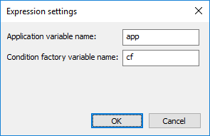
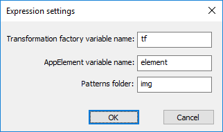
The Expression Settings dialog box is activated by clicking the gear icon at the bottom right of the UltimateRPA Inspector dialog box. The value in the Application Variable Name edit box represents the urpa.App class instance name in the robotic script. The value in the Condition Factory Variable Name edit box represents the urpa.ConditionFactory class name in the robotic script. The values in the Search Function and Type of Action select fields of the UltimateRPA Inspector dialog box are consistent with urpa.AppElement class methods – see the urpa.py interface documentation in Documentation.exe. Use the document icon at the bottom right of the UltimateRPA Inspector dialog box to copy an expression from the Expression edit box to the system clipboard.
After at least one checkbox is activated in the CF column, the left side of the UltimateRPA Inspector dialog box displays a list of GUI elements whose attribute values match the current selection of attributes in the CF column. To process the entire robotic script correctly, or to identify the GUI element correctly when running a robotic script, it is necessary to have a one-element list of GUI elements or to have GUI elements that are uniquely identifiable via the attributes used.
Use the edit box above the GUI element tree to search for GUI elements corresponding to the string entered. You can also run searches using Condition Factory regular expressions , which helps to verify that the regular expression entered is correct. The search box content is a regular expression. When you have finished entering the text, it is transferred as a parameter to the urpa.ConditionFactory.regexp method, which will display a list of all the GUI elements found according to the regex criteria entered.
Some applications do not support the layer which is used to identify GUI elements. In such cases, the Inspector is not displaying individual GUI elements in the element tree on its left side. However, we may use images to identify GUI elements on an application screen. The robot identifies a GUI element by matching the image patterns on the application window. To find a GUI element based on an image you may use the find_first_visual and find_all_visual methods. These methods use an image (png or bmp) or an image pattern to identify a GUI element on an application window. Use the controls on the VisualElement tab in the right part of Inspector to analyze and create inputs patterns for these methods. After Inspector is run, the robotic application graphical interface's recording mode is not active when Inspector's crosshair is moved. This mode is turned on by pressing the Capture Visuals button next to Inspector's crosshair. If this mode is turned on, when you finish working with Inspector's crosshair (by releasing the left mouse button above the robotic application) the current status of the selected robotic application's graphical interface is loaded on to the VisualElement tab's canvas. When work with Inspector's crosshair ends, the area of the selected AppElement is highlighted in green on the canvas.
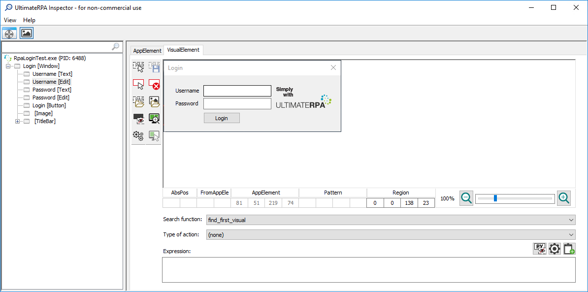
The largest area of the VisualElement tab is occupied by the canvas, on which a screenshot of the robotic application is displayed. The top left corner of the robotic application is always located in the top left corner of the canvas. To the left of the canvas, there are toolbars with buttons, with functions described in Tools for Working with the Canvas. Hovering over individual buttons displays a tooltip with the name of the tool associated with the button. Below the canvas is a status bar displaying current information about the position of the cursor and the individual elements on the canvas. At the end of the status bar, there is a slider to zoom in and out on the canvas. How exactly the status bar behaves is described in chapter VisualElement Tab Status Bar. Below the status bar, there is an Expression field similar to the one on the AppElement tab. It is used to build an expression and allows it to be copied into a robotic script. Control of the form is described in Creating an Output Expression. The current AppElement selected with the crosshair(the green-framed element) can be changed manually by selecting another element in the tree on the left side of Inspector.
The tools for working with canvas are used to manage the pattern (the orange-framed element), the region (red-framed element), etc. The pattern (the orange-framed element) is a visual pattern, i.e. a screenshot crop representing the element of part of the robotic application's graphical interface. The resulting pattern can be stored on disk as a png or bmp file. It is represented by an orange-framed element on the VisualElement tab. When running the robotic script, the pattern is the main input for the creation of the VisualElement object. A region (the red-framed element) is a user-defined area in which tools are to search for a pattern. After a VisualElement tab tool is used to search for a pattern, a GUI element (the green-framed element) is searched for first. This is followed by verification of whether a user region (the red-framed element) is defined. If a user region is defined, Inspector attempts to search for a pattern only in that region. If a user region is not defined, Inspector attempts to search for the pattern (the orange-framed element) in the area of the GUI element (the green-framed element). Technically, the pattern search always moves from the upper left corner of the region to the upper right corner of the region, then continues a line (one pixel) down, from left to right, etc.
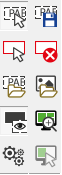
The Select pattern tool is used to define a pattern on the canvas. After enabling the Select pattern button, you can use the cursor or the crosshair over the canvas to define a pattern in the shape of an orange rectangle. The border is not part of the pattern. The pattern is defined by pressing the left mouse button, dragging the mouse, and then releasing the left mouse button over the canvas. After the pattern has been defined, its coordinates relative to the current AppElement (the green-framed element) are updated at the bottom of the canvas. The selected pattern can be canceled by clicking the left mouse button on the canvas.
The Save pattern button is disabled when you first switch to the Visual Inspector tab. It is enabled, after the pattern has been defined, via the Select pattern tool on the canvas. When you click the Save pattern button, the "Save as" dialog box opens. This dialog box allows you to enter the name, format (png or bmp) and location of the file representing the currently selected pattern (image). No frames created with the tools for working with the canvas are saved to the file (image).
The Select region tool allows you to define a custom user region for priority pattern searches using the Load pattern option. After enabling the Select region button, you can use the cursor or the crosshair over the canvas to define a region in the shape of a red rectangle. The region is defined by pressing the left mouse button, dragging the mouse, and then releasing the left mouse button over the canvas. After the region has been defined, its coordinates relative to the current AppElement (the green-framed element) are updated at the bottom of the canvas.
This tool is used to clear a custom user region created using the Select Region tool. The Clear region button is enabled when you create a custom user region using the Select region tool.
The Load pattern tool allows you to retrieve and frame, on the canvas, a pattern created using the Save pattern tool. When you click the Load pattern button, the "Open" dialog box opens. This dialog box allows you to enter the name, format (png or bmp) and location of the file representing a saved pattern (image). After the "Open" dialog box has been filled in and confirmed, Inspector attempts, on the canvas, to find the pattern stored in the file. The pattern search method is similar to invoking urpa.find_first_visual(). If the search is successful, Inspector frames the pattern it has found in orange, as though it had been selected with the Select pattern tool. First, Inspector attempts to find the pattern in the user region created with the Select region tool. If a user region is not created, Inspector attempts to search for the pattern in the area of the current AppElement (the green-framed element). If the pattern is not found in the area of the current AppElement (the green-framed element) either, Inspector attempts to scan the entire screenshot or the area of the entire canvas. If the pattern is found multiple times, only the first pattern found is marked. If the pattern is not found at all, a dialog box is displayed to communicate this.
The Load screenshot button allows you to load a screenshot on the canvas. When you click the Load screenshot button, the "Open" dialog box opens. This dialog box allows you to enter the name, format (png or bmp) and location of the file representing the screenshot. After the "Open" dialog box has been filled in and confirmed, the selected error screenshot is displayed on the canvas.
This button is used to turn the framing of all selected elements on the canvas on and off. When Inspector is run, this option is always enabled.
Use this button to display a detail of the user region (the red-framed element) or the current AppElement (the green-framed element) on the canvas. When this button is pressed, the top left corner of the user region (the red-framed element) appears in the upper left corner of the canvas. If the user region is not defined, the current AppElement (the green-framed element) is displayed in optimal detail. When this button is pressed again, the previous state of the canvas is displayed.
Pressing this button opens a new window, where the transformations described in the chapter on Transformation can be defined.
The AppElement tool allows you to select, on the canvas, a custom AppElement (the green-framed element) that is not in the tree. The Select AppElement tool button is accessible only if you have loaded a screenshot to the canvas using Load screenshot. After enabling the Select AppElement button, you can use the cursor or the crosshair over the canvas to define a custom AppElement in the shape of a green rectangle. The custom AppElement is defined by pressing the left mouse button, dragging the mouse, and then releasing the left mouse button over the canvas. After the custom AppElement has been defined, its coordinates relative to the upper left corner of the canvas are updated at the bottom of the canvas. If the AppElement has been selected with the Select AppElement tool, the coordinate values can be edited to change its area. After the coordinate values have been manually edited, AppElement's frame is automatically adjusted on the canvas so that it corresponds to the newly entered coordinate values.

Displays the coordinates of the cursor position in pixels relative to the upper left corner of the robotic application displayed on the canvas.
Displays the coordinates of the cursor position in pixels relative to the upper left corner of the selected AppElement (the green-framed element).
Displays the coordinates of the current AppElement cursor position in pixels relative to the upper left corner of the robotic application displayed on the canvas. If the AppElement has been selected with the Select AppElement tool, the coordinate values can be edited to change its area. After the coordinate values have been manually edited, AppElement's frame is automatically adjusted on the canvas so that it corresponds to the newly entered coordinate values.
Displays the coordinates of the current pattern (the orange-framed element) selected with the Select pattern tool. The coordinate values are in pixels relative to the upper left corner of the current AppElement (the green-framed element), sequenced as left, top, right, bottom. The coordinate values can be edited manually. After the coordinate values have been manually edited, the pattern's frame is automatically adjusted on the canvas so that it corresponds to the newly entered coordinate values.
Displays the coordinates of the region (the red-framed element) selected with the Select region tool. The coordinate values are in pixels relative to the upper left corner of the current AppElement (the green-framed element), sequenced as left, top, right, bottom. The coordinate values can be edited manually. After the coordinate values have been manually edited, the region's frame is automatically adjusted on the canvas so that it corresponds to the newly entered coordinate values.
In the right part of the status bar, there is a slider for canvas zooming. The current zoom value is displayed to the left of the slider. The canvas zoom levels range from 25% to 800%. The zoom level increments are 25%, 50%, 100%, 200%, 300%, 400%, 500%, 600%, 700%, and 800%. When zooming from 500% to 800%, a pixel grid is displayed on the canvas. You can also zoom on the canvas by holding down the Ctrl button and using the scroll wheel.
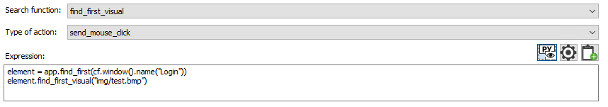
A combo box used to define the method for finding a visual pattern defined via the Load pattern tool. The options available are find_first_visual and find_all_visual.
A combo box used to define the action that is to be performed with the VisualElement. The options available are none, send_mouse_click, send_key, send_text.
When you press this button, Inspector attempts to find the VisualElement according to the expression in the Expression edit box on the screen, in the robotic application's graphical interface. This property behaves similar as for a search in Robot.exe when debug mode is enabled. The action selected in the Type of action combo box is not performed. Only one search cycle is performed at any one time, and if a visual pattern is not found an error message dialog box appears. For it to behave correctly, the robotic application window must not be covered by another application's window. If you use the Load Screenshot tool, you can not use the Highlight expression tool.
After the Settings button is pressed, a new Expression settings window opens, with the option of setting variables for automatic expression generation in the Expression edit box.
Copies the current content of the Expression edit box to the system clipboard.
The Expression edit box displays an automatically generated expression that can then be used in the robotic script. The expression is always displayed after the GUI element has been set and after the Load pattern or Save pattern tool has been used. If the user makes a change in Inspector that affects the automatically generated expression in the Expression edit box, the change is immediately reflected in the content of the Expression edit box. If a GUI element is defined in the AppElement tab using the CF checkboxes, the first line in the Expression edit box generates an expression to find that GUI element. The variable name in the first line of the expression can be defined in the AppElement variable name edit box of the Expression settings dialog box. If AppElement is not defined using the CF checkboxes on the AppElement tab, the expression to find the visual pattern is displayed on the first line. If the path in the Patterns folder edit box is defined in the Expression settings dialog box, this value is inserted in front of the image name.
The Transformation dialog box is enabled by pressing the Transformation button in the toolbar. Transformation in the UltimateRPA tool is used to color the pattern and the screen.

The combo box on the left side of the Transformations dialog box can be used to select the transformation and then add it, via the plus button on the right of the combo box, to the list of transformations that are to be applied to the screenshot on the canvas. If a pattern has already been selected and saved, it appears in the Pattern preview section. The options available are Change colors, Colors inversion and Threshold. The Colors inversion and Threshold options may occur in the transformation list only once. Once the Colors inversion and Threshold options have been defined in the transformation list, they cease to be available in the combo box. There is no limit to the number of Changes colors transformations. Use the arrow buttons on the right of the transformation list to change the order of transformations. After the up arrow button is pressed, the transformation currently marked moves up one line. After the down arrow button is pressed, the transformation currently selected moves down one line. The Show transformation button at the bottom displays a preview showing the application of all transformations together on a screenshot on the canvas. The transformations are applied in the order in which they are listed, from top to bottom. A marked transformation can be deleted from the transformation list by pressing the Delete key. After a transform has been selected in the Transformation list, its settings are displayed in the center part of the Transformations window.
The Change_colors transformation allows selected bitmap colors to be converted to another color. This is used, for example, for the different color shading of a robotic application's menu in the test and production environments so that a single robotic script can be applied to both environments. On the left side of the Change colors transformation settings, From colors is used to define the colors you wish to change on a screenshot on the canvas to another color as part of a single Change colors transformation. The colors to be changed can be defined using the eyedropper or by directly filling in the From colors edit boxes, representing the RGB of one color to be changed. Use the plus button to the left of the eyedropper to add the current color defined in the From boxes edit boxes to the Preview list. After the eyedropper is enabled, by directly clicking the left mouse button in the canvas, you can select a color, which is automatically added to the end of the Preview list. The numeric representations of colors, in RGB format, are displayed in the Preview list. A preview of the color appears in front of the numeric representation. The currently selected color can be removed from the Preview list by pressing the Delete key. Two identical colors cannot be inserted in the Preview list. After a color is marked in the Preview list, a preview is displayed in the Color preview edit box. The right side of the To color edit boxes defines the color to which colors in the Preview list are converted in a single Change colors transformation. For the most common colors, white and black, there are two buttons next to the edit boxes which, when pressed, fill in the appropriate value in the To colors edit boxes. When colors are defined in the To colors or From colors edit boxes, a preview is displayed in the Color preview edit box. If no valid color is defined, there are black diagonals on a white background in the Color preview edit box. This transformation is consistent with the change_colors method from the transformation factory.
The Colors inversion transformation inverts colors (this is consistent with the colors_inversion method from the transformation factory). This transformation does not allow for any settings to be made.
Threshold transformation facilitates bitmap conversion to a bitmap (black and white only). Threshold transformation allows you to set a threshold level from 0 to 1. The default threshold value is set to 0.5. A threshold level value from 0 to 1 indicates the ratio at which the RGB ranges between 0 and 255 are divided into two groups, i.e. which colors will be converted to black and which ones will be converted to white. The Threshold transformation behaves in the same way as the threshold method from the transformation factory.
To analyze the graphical interface of the Java application using UltimateRPA Inspector and its control with UltimateRPA Robot, you must first activate the Java access bridge (JAB) in the Java runtime. After dragging and dropping the UltimateRPA Inspector crosshair over the Java application, it is the root of the tree on the left displays an entry containing the value "java.exe (PID: xxx)". Using Windows System Task Manager (taskmgr.exe) and the PID of the Java process, you must determine the location (path) to the Java runtime environment (file java.exe) which runs Java applications for robotization. If the directory with the java.exe file contains jabswitch.exe file, you must run the command "jabswitch.exe / enable" using the command line (cmd.exe). To check Java access bridge (JAB) activation restart the Java application, drag and drop the UltimateRPA Inspectors crosshair over the Java application. If GUI elements are highlighted in the graphical interface, the Java access bridge (JAB) was enabled correctly. Java Access Bridge (JAB) is not part of its standard installation to Java 1.7. To install the Java interface access bridge (JAB) for older versions of Java can be used automatic installation. For manual installation should be used..